ATTENTION!
whatever I do here, I do on my own motorcycle and I take responsibility for it, my own motorcycle!
If you decide to do something along these lines and break/disarm/annihilate/exterminate your motorcycle, it's totally your own responsibility!
So, as clearly as this can be said: I AM NOT RESPONSIBLE for your damages!!!!
Recently I did the ABS mod to a friend's R1150GS. It went really well.
However we did some unnecessary unbolting, which you do not need to do!
In fact if you follow the IBMWr.org's instructions you will see that they say to try and find the green cable below the fusebox... Well...
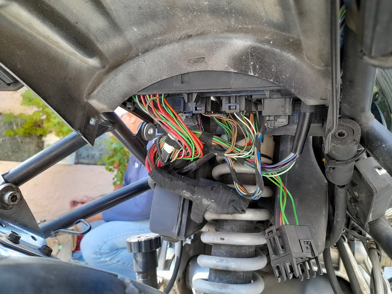
We removed the lower panel of the fusebox and found the famous green wire going from the ABS relay to the Pin 15 at the ABS connector.
Actually we didn't need to do that. Instead I routed my cable from the relay to the ABS connector.
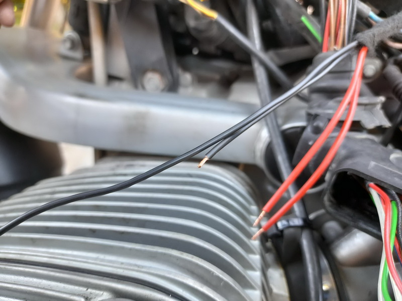
I disassembled the connector, as per the instructions, then found the green cable outside the connector and cut it. Then, I soldered the two cables coming from pins 30 and 87 of the relay. The two cables are red in my case, in the photo above, and it doesnt matter where we solder them.
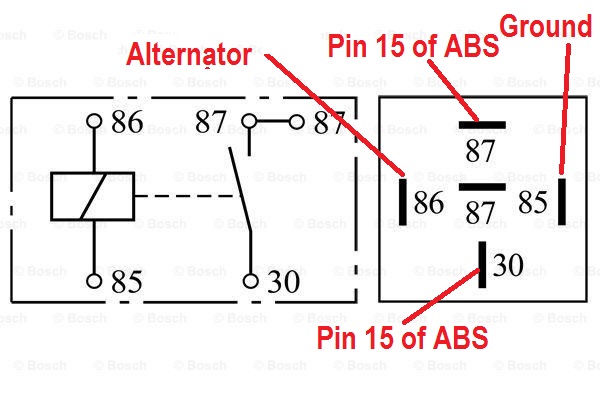
The schematic on how to connect the pins on the relay.
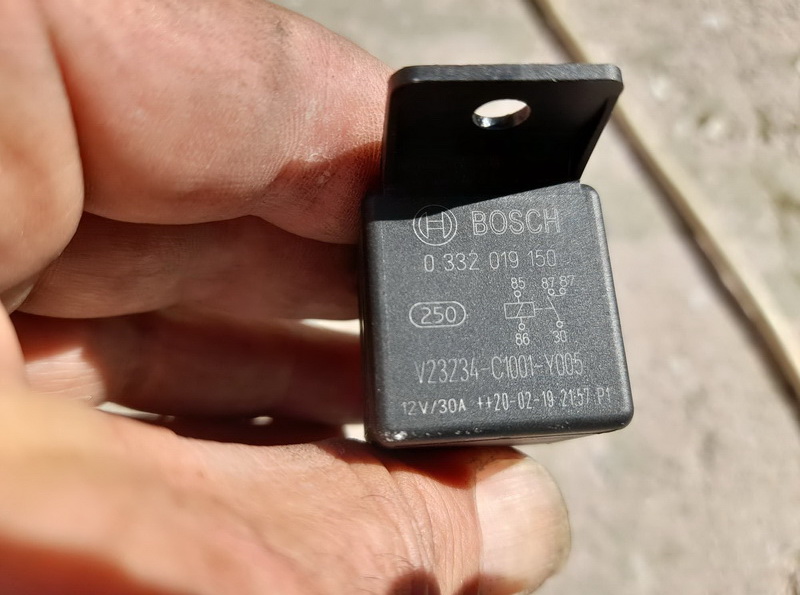
This is the BOSCH relay we got.
Part Number: 0 332 019 150.
Cost is 2,96 euros!!!
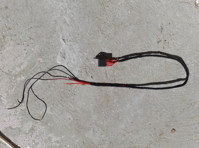
I measured roughly where I would route the cables to the front of the bike, keeping in mind that the relay would be inside the fusebox.
I covered the cables almost all the way with good tape. After I finished connecting all the cables, I added zipties along the frame, to secure the new harness.
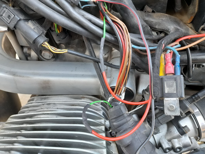
I soldered carefully my red wires to the cut green wire of the Pin 15, well outside of the connector. Covered the solders with heatshrinkable cable, so they are stable and safe. I also covered the exposed wiring of the ABS connector with tape so it's safer and nicer, too!
The relay on the right of the photo is for the 1150's extra driving lights. We had to remove it so we could have access to the ABS connector. After we finished, we bolted it again right where it was before...

I removed the alternator's pin (it sits on the left side of the bike), adn soldered the cable coming from Pin 86 of the relay on the connector cable. Reinstalled this one. With some luck and being very (VERY!) careful it's quite feasible to removbe the pin from its plastic case. After sldering the new wire, ideally you can slide some heat shrink cable over the solder, and then re mount the connector it its plastic case, then reconnect it on the alternator.
I also secured the Ground wire, coming from the relay's pin 85, to one of the ECU bolts.
And it worked first time!